TM 9-2350-261-20-2
R E P L A C E N A T O A U X I L I A R Y P O W E R ( S L A V E ) R E C E P T A C L E
( M 5 7 7 A 2 A N D M 1 0 6 8 O N L Y )
DESCRIPTION
This task covers: Remove (page 9-10).
Install (page 9-11).
INITIAL SETUP
Personnel Required
Unit Mechanic
Tools
General Mechanics Tool Kit (Item 30, App D)
Materials/Parts
Gasket
Gasket
Lockwasher (4)
Lockwasher (4)
Lockwasher (7)
Lockwasher (2)
References
see your -10
Equipment Conditions
Engine stopped/shutdown (See your -10).
Battery ground lead disconnected (page 13-2)
R E M O VE
1.
2.
3.
4.
5.
6.
7.
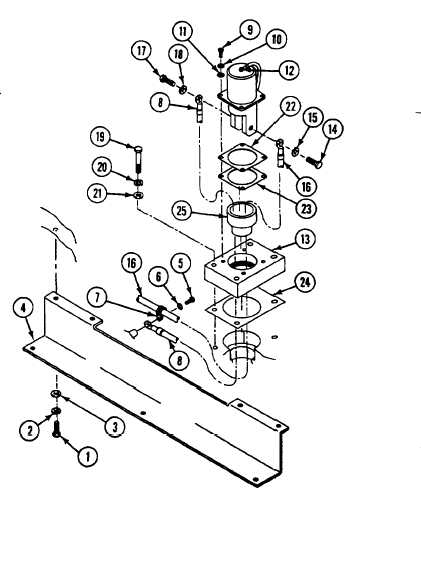
Remove seven screws (1), lockwashers (2),
washers (3), and harness protector (4) from
hull. Discard lockwashers.
Remove screw (5), washer (6), clamp (7), and
circuit 50 lead (8) from hull weldnut.
Remove four screws (9), lockwashers (10),
and washers (11) from receptacle (12).
Discard lockwashers.
Pull receptacle (12) and adapter (13) away
from hull.
Remove screw (14), lockwasher (15), and
circuit 6 lead (16) from positive terminal of
receptacle (12). Discard lockwashers.
Remove screw (17), lockwasher (18), and
circuit 50 lead (8) from negative terminal of
receptacle (12). Discard lockwashers.
Remove four screws (19), lockwashers (20),
and washers (21) from adapter (13). Discard
lockwashers.
8. Remove receptacle (12), gasket (22),
insulator (23), adapter (13), and gasket (24)
from hull. Discard gaskets.
9. Remove insulator bushing (25) from adapter
(13).
9-10
Change 4