TM 9-2350-261-20-2
I N S T A L L
N O TE
Lubricate
connecting
l i n k r o d - e nd
bearings before installation. Use GAA
grease.
13.
14.
15.
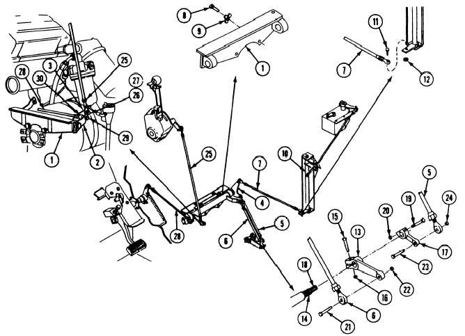
Place transmission cross-shaft bracket (1),
accelerator cross-shaft (2), transmission
cross-shaft (3), bellcrank (4), two
transmission arm links (5 and 6), and
throttle link (7) on transmission as a unit.
Secure with two screws (8) and two new
key washers (9).
Install throttle link (7) on vertical transfer
shaft (10). Secure with screw (11) and new
locknut (12).
Install range selector lever (13) on
transmission shaft (14) with off-set side of
lever toward transmission and clamp-screw
hole aligned with flat on shaft. Secure with
screw (15) and new locknut (16).
16.
17.
18.
19.
20.
Install throttle valve lever (17) on
transmission shaft (18) with off-set side of
lever away from transmission and
clamp-screw hole aligned with flat on shaft.
Secure with screw (19) and new
locknut (20).
Install range selector link (6) on
transmission arm (13). Secure with
screw (21) and new locknut (22).
Install throttle valve link (5) on
transmission arm (17). Secure with
screw (23) and new locknut (24).
Install transmission range selector to
—
cross-shaft link (25) on transmission arm
(3). Secure with SCrew (26) and new lock-
nut (27).
Install accelerator link (28) on accelerator
cross-shaft arm (2). Secure with screw (29)
and new locknut (30).
GO TO NEXT PAGE
23-27
I
-