TM 9-2350-261-20-2
CLEAN, INSPECT, AND REPLACE
9. Check pins, pedal mount, and pedal link.
Replace parts that are cracked or have worn
pivot holes.
I N S T A L L
10.
11.
12.
13.
14.
15.
16.
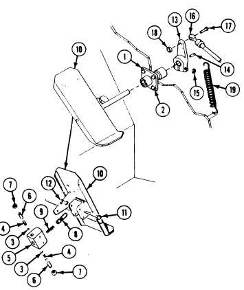
Install guide (1) on power plant
compartment. Secure with four screws (2).
Install two ball bearings (3) and springs (4)
in pedal detent block (5). Secure with two
set screws (6).
Install two nuts (7) on
Install plunger (8) and
detent block (5).
two set screws (6).
spring (9) in pedal
Install pedal detent block (5) on pedal (10).
Secure with two screws (11) and new
locknuts (12).
Use spring scale to adjust detent plunger
(page 23-34. Use pressure to 35-40
pounds (16-18 kg).
Install pedal assembly (10) in guide (l).
17.
18.
19.
Place bellcrank (13) and woodruff key (14)
on pedal assembly (10) shaft. Tighten
nut (15).
Install link (16) on bellcrank (13). Secure
with screw (17) and new locknut (18).
Connect return spring (19) to bellcrank (13).
FOLLOW-THROUGH STEPS
1.
2.
3.
4,
Install lower accelerator pedal (page 23-22).
5.
Install driver’s power plant access panel
6.
(page 24-25).
7.
Install driver’s seat (page 24-127).
Close power plant front access door and raise 8.
trim vane (see your -10).
Raise and lock ramp (see your -10).
Start engine (see your -10).
Check that upper accelerator pedal operates
properly.
Stop/shutdown engine.
END OF TASK
23-24