TM 9-2350-261-20-2
R E P L A C E U P P E R A C C E L E R A T O R P E D A L A S S E M B LY
D E S C R I P T I O N
This task covers:
Remove (page 23-23).
Clean, Inspect, and Replace (page 23-24).
Install (page 3-24).
I N I T I A L S E T U P
Tools:
General Mechanics Tool Kit (Item 30, App D)
Weighing Scale (Item 61, App D)
Materials/Parts:
Self-locking nut
Self-locking nut (2)
Personnel Required:
Unit Mechanic
References
See your -10
Equipment Conditions
Carrier blocked (see your -10)
Engine stopped/shutdown (see your -10)
Ramp lowered (see your -10)
Trim vane lowered and power plant front
access door open (see your -10)
Driver’s power plant access panel removed
(page 24-25)
Driver’s seat removed (page 24-127)
Remove lower accelerator pedal (page 23-22)
R E M O V E
1.
2.
3.
4.
5.
6.
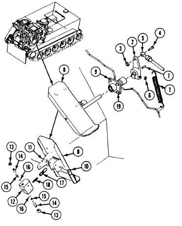
Disconnect return spring (1) from
bellcrank (2).
Remove locknut (3), screw (4), and link (5)
from bellcrank (2). Discard locknut.
Loosen nut (6). Remove bellcrank (2) and
woodruff key (7) from pedal assembly (8).
Remove pedal (8) from guide (9).
CAUTION
Detent plunger and spring will fall out if
detent block is turned over during
removal
Remove two screws (10), locknuts (11), and
pedal detent block (12) from pedal (8).
Discard locknuts.
Remove two nuts (13) and set screws (14)
from detent block ( 12). Then turn detent
block (12) to allow two springs (15) and ball
bearings (16) to slide out.
8. Remove four screws (19) and remove guide
(9) from power plant compartment.
Remove plunger ( 17) and spring (18) from
detent block (12).
GO TO NEXT PAGE
23-23
7.