TM 9-2350-261-20-2
R E P L A C E D I F F E R E N T I A L C R O S S - S H A F T L I N K S
INITIAL SETUP
Tools:
References:
General Mechanics Tool Kit (Item 30, App D)
See your -10
Materials/Parts:
Equipment Conditions:
Cotter pin (4)
Engine stopped/shutdown (see your -10)
Carrier blocked (see your -10)
Personnel Required:
Trim vane lowered and power plant front
Unit Mechanic
access door open (see your -10)
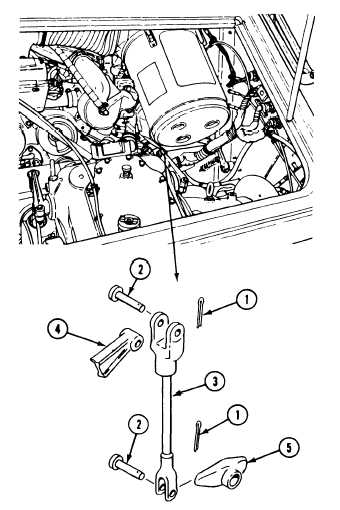
R E M O V E
1. Disconnect two return springs (page 23-2).
2. Remove four cotter pins (1), clevis pins (2),
and two links (3) from differential steering
levers (4) and differential cross-shafts (5).
Discard cotter pins.
C L E A N , I N S P E C T , A N D R E P A I R
3.
4.
5.
6.
Check link rods. Replace cracked, bent, or
broken links.
Check link clevises. Replace links with
cracked or worn mounting holes.
Check clevis pins. Replace worn or grooved
clevis pins.
Check springs. Replace cracked or worn
springs .
I N S T A L L
7. Install two links (3) to differential steering
levers (4) and differential cross-shafts (5).
Secure with four clevis pins (2) and new
cotter pins (1).
8. Adjust linkage (page 23-2).
9. Connect two return springs (page 23-2).
FOLLOW-THROUGH STEPS
1. Close power plant front access door and raise
2. Operate steering levers to check that
trim vane (see your -10).
differential cross-shaft links operates properly.
END OF TASK
23-19