TM 9-2350-261-20-2
R E P L A C E D I F F E R E N T I A L S T E E R I N G B R A K E L E V E R S
I N I T I A L S E T U P
Tools:
References:
General Mechanics Tool Kit (Item 30, App D)
See your -10
Torque Wrench (Item 95, App D)
Equipment Conditions:
Materials/Parts:
Engine stopped/shutdown (see your -10)
Self-locking nut (2)
Carrier blocked (see your -10)
Trim vane lowered and power plant front
Personnel Required:
access door open (see your -10)
Unit Mechanic
REMOVE
INSTALL
1.
2.
3.
Disconnect two return springs (page 23-2).
6.
Disconnect two differential links (page 23-19).
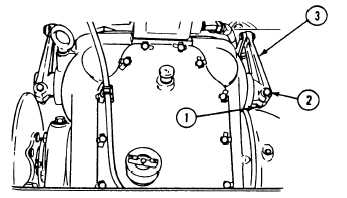
Remove two locknuts (1), screws (2), and two
7.
brake levers (3) from differential brake lever
shafts. Discard locknuts.
C L E A N , I N S P E C T , A N D R E P A IR
4.
5.
Check levers. Replace
worn clevis pin holes.
Check levers. Replace
chipped splines.
9.
levers with cracked or
10.
levers with damaged or
Install two levers (3) on differential brake
lever shafts. Secure with two screws (2) and
new locknuts (1).
Tighten nuts (1) to 360-420 lb-in torque.
Use torque wrench.
Connect two differential links (page 23-19).
Adjust linkage (page 23-2).
Connect two return springs (page 23-2).
FOLLOW-THROUGH STEPS
1. Close power plant front access door and raise
2. Operate steering levers to check that
trim vane (see your –10).
differential steering brake levers operate
properly.
23-20
END OF TASK
8.