TM 9-2350-261-20-2
R E P L A C E D I F F E R E N T I A L C R O S S - S H A F T S A N D B E A R I N G S
D E S C R I P T I ON
This task covers:
Remove (page 23-16).
Clean, Inspect, and Repair (page 23–17).
Install (page 23-17).
INITIAL SETUP
Tools:
References:
General Mechanics Tool Kit (Item 30, App D)
See your -10
Snap Ring Pliers (Item 45, App D)
See your LO
Materials/Parts:
Equipment Conditions:
Cotter pin (4)
Engine stopped/shutdown (see your -10)
Self-locking nut (3)
Carrier blocked (see your -10) -
Self-locking nut (4)
Trim vane lowered and power plant front
Personnel Required:
access door open (see your -10)
Air cleaner housing and element removed
.
Unit Mechanic
(page 7-7)
Helper (H)
Oil can bracket removed (page 24-237).
R E M O V E
4.
1.
2.
3.
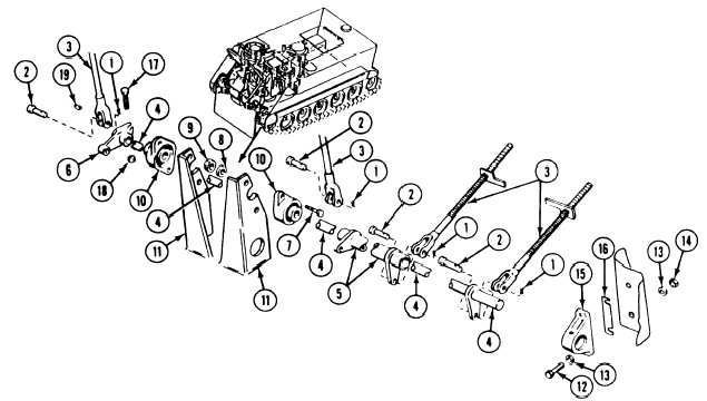
Disconnect two return springs (page 23-2).
Remove four cotter pins (1), clevis pins (2),
and links (3) from differential and steering
5.
lever cross-shafts (4 and 5) and link arm (6).
Discard cotter pins.
Remove four screws (7), washers (8), and
locknuts (9) that secure two bearings (10) to
6.
two brackets (11). Discard
locknuts.
Remove two screws (12), four washers (13),
and two locknuts (14) that secure bearing
(15) and shim (16) to driver’s compartment
bulkhead. Discard locknuts.
Remove differential and steering cross-shafts
(4 and 5), bearings (10 and 15), and link
arm (6) from power plant compartment as a
unit.
Remove screw (17), locknut (18), and link
arm (6) from cross-shaft (4). Remove wood-
ruff key (19) from cross-shaft. Discard
locknut.
23-16