7 .
8 .
9 .
10.
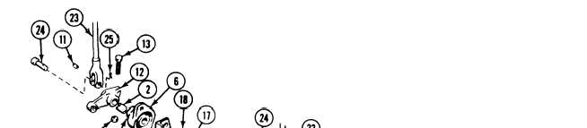
Remove bearing (1) from cross-shaft (2).
Loosen four set screws (3) in two bearing
collars (4).
Separate cross-shafts (2 and 5), two bear-
ings (6), and two thrust washers (7).
Remove two retaining rings (8), bearing (9),
and lubrication fitting (10) from bearing (1).
CLEAN, INSPECT, AND REPAIR
11. Check links. Replace links with cracks,
breaks, or stripped threads.
12. Check bearings, retaining rings, and fittings
for cracks or wear. Replace damaged parts.
I N S T A LL
13. Install bearing (9) in bearing (1). Secure
with two retaining rings (8).
14. Install lubrication fitting (10) in bearing (1).
15.
16.
17.
18.
19.
20.
21.
22.
TM 9-2350-261-20-2
Assemble two cross–shafts (2 and 5), two
bearings (6), two thrust washers ( 7),
bearing ( 1), woodruff key ( 11), and
arm (12).
Install screw ( 13)
link arm (12). Do
and new locknut
not tighten nut.
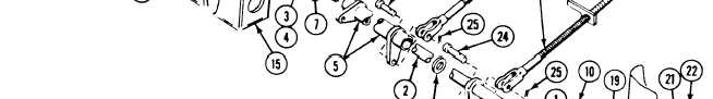
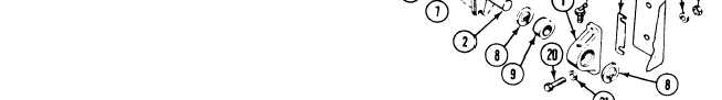
Place cross-shafts (2 and 5), two bearings
(6), and bearing (1) as a unit on two
brackets (15).
Install two bearings (6) on two brackets
(15). Secure with four screws ( 16), washers
(17), and new locknuts (18).
Install bearing (1) and shim ( 19) to driver’s
compartment bulkhead. Secure with two
screws (20), four washers (21 ), and two new
locknuts ( 22).
Install four links (23) to cross-shafts (2 and
5) and link arm ( 12). Secure with four
clevis pins (24) and new cotter pins (25).
Tighten four set screws (3) in two bearing
collars (4) .
Tighten nut (14) on link arm (12).
link
(14) in
GO TO NEXT PAGE
23-17