TM 9-2350-261-20-2
CLEAN, INSPECT, AND REPLACE
5. Check fittings and relief valve for wear and
damage. Replace if needed,
6. Clean and check bearings (TM 9-214). Re-
place bad bearings and cups.
I N S T A LL
7.
8.
9.
10,
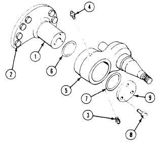
Place spindle (1) on hull. Secure with eight
screws (2). Tighten screws to 315-325 lb-ft
(427-441 N·m) torque. Use torque wrench.
Apply light coat of sealing compound to
threads of relief valve (3) and grease fitting
(4). Install valve and fitting in idler arm (5)
with fitting (4) facing forward.
Apply continuous coat of grease on shaft of
spindle (1) and bearing surface inside
arm (5).
Install new inner packing (6) and new outer
packing (7) in arm (5).
FOLLOW-THROUGH STEPS
11.
12.
13.
Place track tension adjuster (page 22-24 ) on
shaft at rear of arm (5). Install arm on
spindle (1).
Install retainer (9) on spindle (1) with
cutout portion at bottom of groove in arm.
Secure with three screws (8). Tighten screws
to 75–80 lb-ft (102–108 N·m) torque. Use
torque wrench.
Fill idler arm with grease (see your LO).
1.
2.
3.
4.
Connect track tension adjuster to idler arm
5. Install track shroud and covers (page 22–2).
(page 22-24).
6. Road test earner (page 2-45) to check that
Install road wheel hub (page 22-9).
idler wheel arm is installed properly.
Install idler wheel (page 22-16).
7. Stop engine (see your –10).
Connect track and adjust tension
(see your –10).
END OF TASK
22-23