CLEAN, INSPECT, AND REPLACE
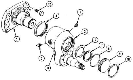
6. Check fittings and safety relief valve for wear
and damage. Replace if needed.
7. Clean and check retaining rings and spacer
for damage. Replace if needed.
I N S T A LL
8. Apply light coat of sealing compound on
threads of safety relief valve (1) and
fitting (2) .
N O T E
Install fitting on the forward side of idler
arm (see your LO).
9. Install safety relief valve (1) and fitting (2)
in idler arm (3).
10.
11.
12.
13.
14,
TM 9-2350-261-20-2
Install new seal (4) and idler arm (3) on
idler wheel assembly (5).
Install spacer (6), retaining ring (7), and
new preformed packing (8) in idler arm (3).
Install access cover (9) and retaining ring
(10) in idler arm (3).
Place track tension adjuster on shaft (11) at
rear of idler arm (3). Align idler wheel as-
sembly (5) with holes on hull. Secure with
eight screws (12). Tighten screws to
315-325 lb-ft (427-441 N·m) torque. Use
torque
wrench.
.
Fill idler arm (3) with grease (see your LO).
FOLLOW-THROUGH STEPS
1. Connect track tension adjuster to idler arm
4.
(page 22-24).
2. Install road wheel hub (page 22-9).
5
Connect track and adjust tension
See your -10),
Install track shroud and covers (page 22-2).
3. Install idler wheel (page 22-16).
6. Road test carrier (page 2-45) to check that
idler wheel arm is installed properly.
7. Stop/shutdown engine (see your -10).
END OF TASK
22-21