TM 9-2350-261-20-2
REPLACE REAR UTILITY OUTLET RECEPTACLES
(M577A2 AND M1068 ONLY)
DESCRIPTION
This task covers:
Remove (page 17-9).
Clean, Inspect, and Replace (page 17-9).
Install (page 17-10).
INITIAL SETUP
Tools:
References:
General Mechanics Tool Kit (Item 30, App D)
See your -10
Materials/Parts:
Equipment Conditions:
Lockwasher (5)
Engine stopped/shutdown (see your -10)
Receptacle gasket
Ramp lowered (see your -10)
Carrier blocked (see your -10)
Personnel Required:
Battery ground lead disconnected (page 13-2)
Unit Mechanic
REMOVE
1.
2.
3.
4.
5.
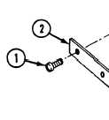
Remove two screws (1) retainer strip (2)
and rubber shield (3) from hull mount (4).
Disconnect circuit 37A lead (5) (right recep-
tacle) or circuit 37B lead (5) (left receptacle)
from receptacle lead (6).
Remove clip (7) and rear main wiring har-
ness (8) from cradle (9).
Remove screw (10), cradle (9), ground lead
(11), and lockwasher (12) from hull weldnut.
Discard lockwasher.
Remove four screws (13), lockwashers (14),
chain (15), receptacle (16), and gasket (17)
from rear bulkhead. Discard gasket and
lockwashers.
6. Remove cap (18)
CLEAN, INSPECT, AND REPLACE
7.
8.
from receptacle (16).
Check leads. Replace frayed, cracked, or
broken leads (page 14-3).
Check connectors. Replace cracked or broken
connectors (page 14-3).
GO TO NEXT PAGE
Change 3
17-9