TM 9-2350-261-20-1
R E P L A C E F U E L S U P P L Y H O S E S , T U B E S A N D F I T T I N GS
( M 5 7 7 A 2 A N D M 1 0 6 8 O N L Y)
DESCRIPTION
This task covers:
Remove (page 6-60).
Install (page 6-63).
INITIAL SETUP
Tools:
General Mechanics Tool kit item 30, APP D)
Materials/Parts:
Sealing compound (Item 49, APP C)
Wiping rag (Item 61, App C)
Lockwasher (9)
Lockwasher (4)
Self-locking nut (4)
Personnel Required:
Unit Mechanic
References:
See your -10
Equipment Conditions:
Engine stopped/shutdown and ramp lowered
(see your -10)
Carrier blocked (see your -10)
Battery ground lead disconnected (page 13-2)
Fuel tanks drained (page 6-50)
Power plant rear access panel removed
(page 24-29)
Rear compartment floor plates removed
(page 24-37)
REMOVE
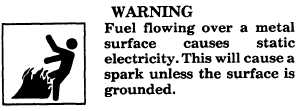
NOTE
Use wiping rag to wipe up any spilled fuel.
2.
3.
4.
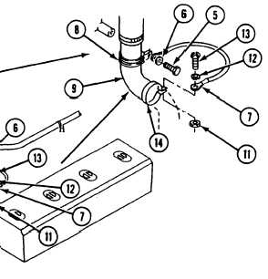
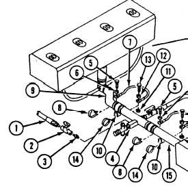
Remove shutoff valve (2) and nipple (3) from
tube (4).
Remove four screws (5) and lockwashers (6)
that secure four ground leads (7), clamps (8),
and two elbows (9) to four weldnuts (10).
Discard lockwashers.
Remove four locknuts (11), lockwashers (12),
and screws (13) that secure four leads (7)
and clamps (14) to elbows (9) and tubes
(4 and 15). Discard locknuts and lockwashers.
1. Disconnect personnel heater fuel hose (1) from
shutoff valve (2), if installed.
6-60
Change 3