TM 9-2350-261-20-1
R E P L A C E F U E L T A N K A C C E S S C O V E R S
( M 5 7 7 A 2 A N D M 1 0 6 8 O N L Y )
INITIAL SETUP
Tools:
General Mechanics Tool Kit (Item 30, App D)
Socket Wrench Set (Item 88, App D)
Torque Wrench (Item 99, App D)
Materials/Parts:
Gasket
Locking plate bolt (8)
Personnel Required:
Unit Mechanic
References:
See your -10
See your LO
Equipment Conditions:
Engine stopped/shutdown (see your -10)
Carrier blocked (see your -10)
Ramp lowered (see your -10)
Battery ground lead disconnected (page 13-2)
Map board removed (see your -10)
Work tables removed
(page 24-173, 24-175, or 24-178)
1.
2.
3.
N O T E
Left and right fuel tank access covers are
the same. The following steps apply to one
cover.
Drain fuel tank below access cover level
(page 6-50).
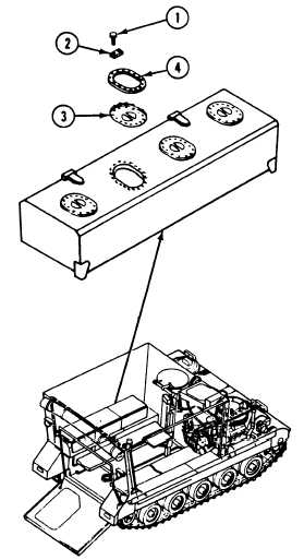
Remove 16 screws (1) and 8 locking plate
bolts (2) that secure fuel tank access cover
(3) and gasket (4) to fuel tank. Discard
locking plate bolts.
Remove fuel tank access cover (3) and gasket
(4) from fuel tank. Discard gasket.
INSTALL
4.
5.
6.
7.
Place new gasket (4) on access cover (3).
Place cover (3) and new gasket (4) inside fuel
tank opening. Secure with 8 new locking
plate bolts (2) and 16 screws (l).
Tighten 16 screws (1) to 36-48 lb-in
(41-55 CMKG) torque. Use torque wench and
socket wrench set.
Fill fuel tank (see your -10). Check tank for
leaks.
GO TO NEXT PAGE
Change 3
6-57
R E M O V E


