55.
56.
67.
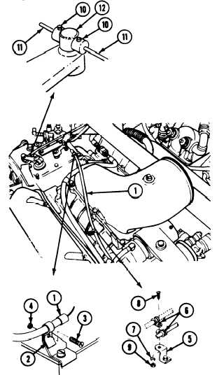
Install control cable (1) in clamp (2). Secure
with screw (3) and nut (4).
Fasten control cable (1) to engine
cylinder-head cover bracket (5) with two
clamps (6), washer (7), screw (8), and
nut (9).
Tighten setscrews (10) that
secures fuel
cutoff control cable (11) to governor arm
pin (12).
58.
59.
TM 9-2350-261-20-1
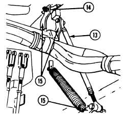
Connect accelerator pedal linkage (13) and
range selector linkage (14) to bell-
cranks (15).
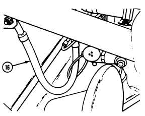
Connect starter ground lead (16)
to hull.
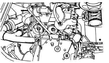
60. Connect differential oil inlet hose (17) to
differential.
61. Connect differential oil temperature lead (18)
to differential.
GO TO NEXT PAGE
5-21