TM 9-2350-261-20-1
H O O K U P / R E M O V E S T E / I C E - R F O R P O W ER
INITIAL SETUP
Tools:
References:
STE/ICE-R Test Set (Item 71.1, App D)
See your -10
TM 9-4910-571-12&P
Personnel Required:
Unit Mechanic
Equipment Conditions:
Engine stopped (see your -10)
Carrier blocked (see your -10)
HOOK UP
1.
2.
3.
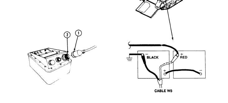
Remove VTM and power cable W5 from
transit case.
Pull VTM circuit breaker to OFF.
Install plug W5P1 (1) on VTM jack J1 (2).
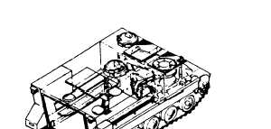
4. Remove battery cover. See CHECK CARRIER
BATTERIESS in your -10.
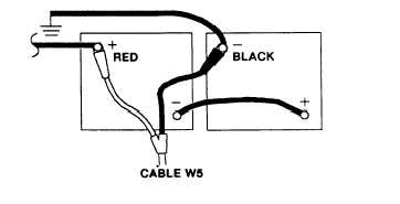
5. Connect red clip of power cable W5 to positive
terminal of battery.
6. Connect black clip of power cable W5 to
negative terminal of battery.
GO TO NEXT PAGE
Change 1
3-275