TM 9-2350-261-20-1
1.
2.
3.
4.
5.
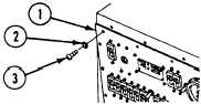
Turn MASTER SWITCH to OFF (see your –10).
Remove ten screws (1) and lockwashers (2), and lower
faceplate (3). Discard lockwashers.
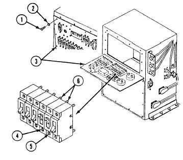
Turn ON DC RIGHT OUTLETS circuit breakers CB14
(4) and CB15 (5).
Measure resistance between terminals 1 and 2 (6) of
circuit breakers CB14 (4) and CB15 (5).
Does multimeter read 0 ohms for each measurement?
1.
2.
Raise faceplate (1) and secure to Power Control Enclo-
sure with ten new lockwashers (2) and screws (3).
Go to: Power Control Enclosure A1 DC Input/Output
Inoperative (page 3-226.1).
N O TE
Resistance in CB14 and
CB15 should be 0 ohms. If
any resistance is present,
replace that CB.
1. Replace circuit breakers
CB14 and/or CB15
(page 40.1-33).
2. Verify no faults found.
3-226.34
Change 3