TM 9-2350-287-20-1
2-22. SIMPLIFIED TEST EQUIPMENT FOR INTERNAL COMBUSTION
ENGINES (STE/ICE) (continued).
b. STE/ICE TROUBLESHOOTING - (continued).
(13) FUEL SUPPLY PRESSURE - (DCA AND TK)
TEST 24 (continued).
Continued from step B
Do test 26 (para 2-22.b(22)) and if no pressure
is indicated, do test 49 (para 2-22.b(7)). If
engine will not start and pressure is 0 psi, check
engine driven fuel pump shaft (para 4-7).
C. 1. Turn MASTER switch to OFF (refer to TM 9-
2350-287-10).
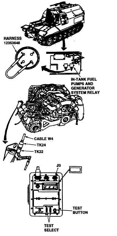
2. Remove harness 12353646 from in-tank fuel
pumps and generator system relay.
3. Place a jumper wire from socket A to socket
c.
4. Install red-striped transducer TK22 and
adapter TK24 at the inlet side of the primary fuel
filter.
5. Connect DCA cable W4 connector P1 to
connector J3 on VTM.
6. Connect DCA cable W4 connector P2 to
transducer TK22.
7. Turn MASTER switch to ON (refer to TM 9-
2350287-1
0).
8. Enter 49 into TEST SELECT, then press and
release TEST button.
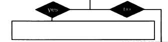
Does VTM reading show 4 psi?
Go to para 2-19.h(5).
D. 1. Turn MASTER switch to OFF (refer to TM 9-
2350-287-10).
2. Remove the jumper wire and reconnect har-
ness 12353646 to in-tank fuel pumps and gen-
erator system relay.
3. Turn MASTER switch to ON and start engine
(refer to TM 9-2350-287-10).
4. Enter 49 into TEST SELECT and press TEST
button.
5. Hold engine speed at 1200 RPM.
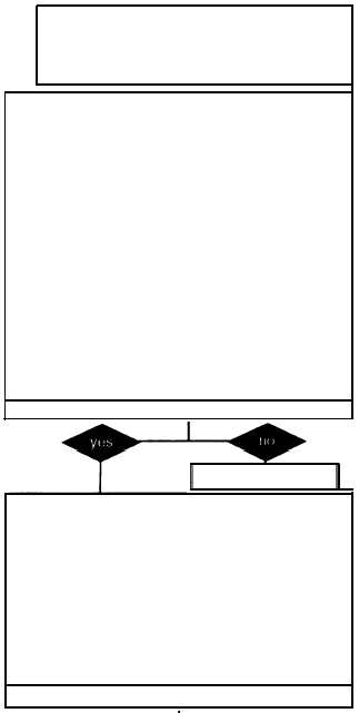
Is a pressure of 1.2 psi held?
Fault does not exist as indicated. Recheck
fault symptom.
Do test 26 (para 2-22.b(22)). If test passes,
replace engine driven fuel pump (para 4-7).
END OF TASK
2-426