2-19. TROUBLESHOOTING CHART (continued).
w. AFES, CREW (continued).
(7) AFES MEGOMETER TROUBLESHOOTING
PROCEDURES.
Initial Setup:
Tools/test Equipment:
• Crew AFES Test/Alarm panel MAINT switch in
• Megometer (Item 37, Appendix 1)
maintenance position (para 21-3).
• Crew AFES fire extinguisher bottle harnesses
Equipment Conditions:
disconnected (para 7-77).
l MASTER switch set to OFF (refer to
TM 9-2350-287-10).
NOTE
l Instead of using multimeter
for voltage check, STE/lCE
troubleshooting,
INDIVIDUAL
BATTERY VOLTAGE TEST-TEST
89 maybe performed.
l Instead of using multi meter
for continuity check, STE/lCE
troubleshooting, TEST 91 may
be performed.
A. 1. Make sure the green POWER ON lamp on
the crew T/A panel is off, indicating that power
has been removed from the AFES system.
NOTE
The W3P1 connector is disconnected
during these tests.
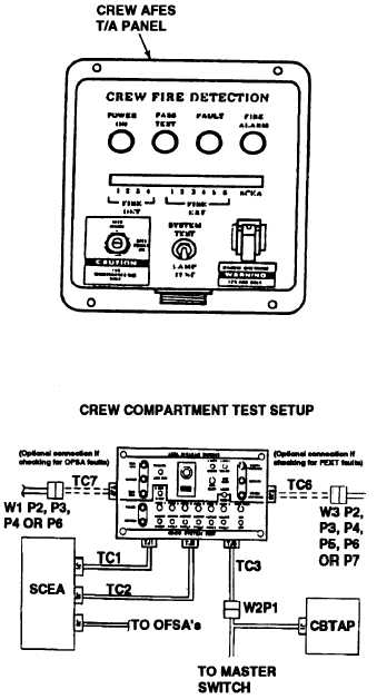
2. Connect the test box to the SCEA and W2
wiring harness using test cables TC1, TC2,
and TC3 as shown in figure 1.
3. Set the test box switches as follows:
a. All fire extinguishers (FEXT 1-6) to
ACTIVE.
b. VENT FAN to ON.
c. CREW switch to 4 EXT or 6 EXT, depend
ing on whether the vehicle has a four
extinguisher system or a six-extinguish
system.
4. Turn MASTER switch ON (refer to TM 9-
2350-287-10).
Continued on next page
2-361
TM 9-2350-287-20-1