TM 9-2350-287-20-1
12-19. TROUBLESHOOTING CHART (continued).
i
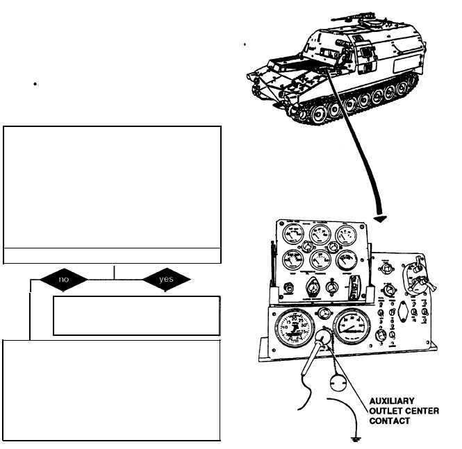
AUXILIARY OUTLET (continued).
(1) AUXILIARY OUTLET FAILS TO OPERATE. All other
electrical systems operate.
Initial Setup:
Tool/Test Equipment:
Equipment Conditions:
Digital Multimeter (DMM) (Item 13, Appendix 1)
MASTER switch set to OFF (refer to TM
General mechanic’s tool kit (Item 24,
9-2350-287-10).
Appendix 1)
NOTE
l Instead of using multi meter
for voltage check, STE/lCE
troubleshooting, INDIVIDUAL
BATTERY VOLTAGE TEST-TEST
89 maybe performed.
Instead of using multi meter
for continuity check, STE/lCE
troubleshooting, TEST 91 may
be performed.
A. 1. Connect red multimeter lead on auxiliary
outlet center contact and ground black lead to
outlet housing.
2. Turn MASTER switch ON (refer to TM 9-
2350-287-10).
3. Check for 24 + 3 vdc.
4. Turn MASTER switch OFF (refer to TM 9-
2350-287-10).
Is voltage indicated?
Fault is with the item being connected
to auxiliary outlet. Verify problem is
solved.
B. 1. Stow portable instrument panel in outside
mounting bracket.
2. Disconnect lead 37 from auxiliary outlet
connector.
3. Place multimeter red lead in 37 connector
socket of harness 12330252 and ground black
lead.
Continued on next page
2-213