TM 9-235-287-20-1
2-19. TROUBLESHOOTING CHART (continued).
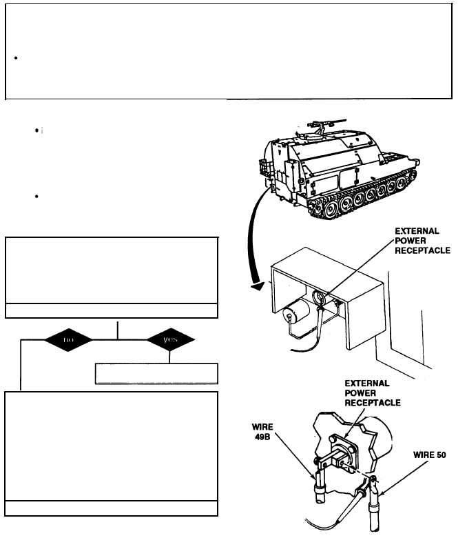
i.
NATO SLAVE RECEPTACLES (continued).
(2) NO POWER AT INTERNAL OR EXTERNAL
POWER RECEPTACLE .
Initial Setup:
Tools/Test Equipment:
Equipment Conditions:
l Digital multimeter (DMM) (Item 13, Appendix 1)
l MASTER switch set to OFF (refer to TM
General mechanic’s tool kit (Item 24,
9-2350-287-1 0).
Appendix 1)
Personnel Required: Two
NOTE
Instead of using multi meter
for voltage
check, STE/lCE
troubleshooting, INDIVIDUAL
BATTERY VOLTAGE TEST-TEST
89 maybe performed.
Instead of using multi meter
for continuity check, STE/lCE
troubleshooting, TEST 91 may
be performed.
A. 1. Place multimeter red lead on external
power receptacle contact and ground black
lead.
2. Check for 24 + 3 vdc.
Is voltage indicated?
Verify problem is solved.
B. 1. Disconnect batteries (para 7-41).
2. Disconnect wire 49B and wire 50 of wire
harness 12376573 from external power re-
ceptacle.
3. Place red lead of multimeter to wire 50
terminal and ground black lead and check for
continuity.
Is continuity indicated?
Continued on next page
2-209


