TM 9-2350-287-20-1
12-19. TROUBLESHOOTING CHART (continued).
f.
GENERATOR (continued).
(1) GENERATOR FAILS TO CHARGE BATTERIES.
GAGE INDICATES NOT CHARGING, UNSTEADY,
OR INACCURATE READING.
Initial Setup:
TooIs/Test Equipment:
•Transmission access doors open (refer to
• Digital multimeter (DMM) (Item 13, Appendix 1)
TM 9-2350-287-10).
•General mechanic’s tool kit (Item 24,
• Engine intake grille open (refer to
Appendix 1)
TM 9-2350-287-10).
Personnel Required: Two
Equipment Conditions:
•Battery access doors open (refer to
TM 9-2350-287-10).
NOTE
l Instead of using multi meter
for voltage
check, STE/lCE
troubleshooting,
INDIVIDUAL
BATTERY VOLTAGE TEST-TEST
89 maybe performed.
l Instead of using multi meter
for continuity check, STE/lCE
troubleshooting, TEST 91 may
be performed.
• As an alternative to doing
the
following
procedures,
perform STE/lCE troubleshooting,
ALTERNATOR OUTPUT VOLTAGE
(DC) - TEST 82, GENERATOR
FIELD VOLTAGE - TEST 83, and
GENERATOR NEGATIVE CABLE
DROP - TEST 84.
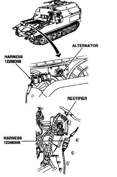
A. 1. Disconnect harness 12268308 from alter-
nator and rectifier.
2. Check continuity of harness 12268308 at
the following locations:
ALTERNATOR
RECTIFIER
CONNECTOR
To
CONNECTOR
SOCKET A
PIN A
SOCKET B
PIN B
SOCKET C
PIN C
SOCKET D
PIN D
SOCKET F
PIN E
Is continuity indicated in all circuits?
Continued on next page
2-88