TM 9-2350-287-20-1
2-19. TROUBLESHOOTING CHART (continued).
f. GENERATOR.
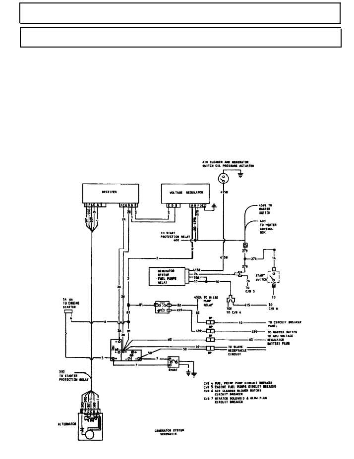
The generator circuit consists of the alternator, voltage regulator, rectifier, master relay, vehicle batteries, air
cleaner/generator system relay switch, starter switch, generator system and fuel pumps relay, and circuit
breakers 4,5,6, and 7. The relationship of these components is shown in the diagram below.
When the MASTER switch is turned ON, 24 vdc is supplied from the batteries through the master relay, through
circuit 82/10 to the circuit breaker panels. Voltage is supplied to the voltage regulator C/B no. 7 (starter solenoid
and glow plug circuit breaker). When engine is cranked and oil pressure reaches 4-8 psi, the oil pressure
actuated air cleaner and generator switch closes, causing the fuel pump/generator relay to close. This closes
a circuit in the voltage regulator and the alternator begins operating and supplying voltage to charge the
batteries and operate all electrical components of the vehicle.
2-87