TM 9-2350-287-20-1
12-19. TROUBLESHOOTING CHART (continued).
1
!
d. ENGINE - ELECTRICAL SYSTEM (continued).
(3) ENGINE CRANKS, BUT WILL NOT START.
Initial Setup:
Tools/Test Equipment:
Equipment Conditions:
• Digital multimeter (DMM) (Item 13, Appendix 1)
• MASTER switch set to OFF (refer to
•General mechanic’s tool kit (Item 24,
TM 9-2350-287-10).
Appendix 1)
•Portable instrument panel stowed in outside
position (refer to TM 9-2350-287-10).
Materiais/Parts:
• Lockwashers (Item 164, Appendix H)
NOTE
• Instead of using multimeter for voltage
check, STE/lCE troubleshooting,
INDIVIDUAL BATTERY VOLTAGE
TEST-TEST 89 maybe performed.
• Instead
of
using
multimeter
for continuity check, STE/lCE
troubleshooting, TEST 91 may
be performed.
A. 1. Remove 12 screws, Iockwashers, and
access panel in driver compartment. Dis-
card Iockwashers.
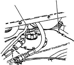
2. Disconnect wire 76 from left in-tank fuel
pump.
3. Place multimeter red lead in wire 76 and
black lead to ground.
4. Turn MASTER switch and hold FUEL
PRIME switch ON (refer to TM 9-2350-287-
10), check wire 76 for voltage (24 ± 3 vdc).
5. Turn MASTER switch and FUEL PRIME
switch OFF (refer to TM 9-2350-287-10).
Is voltage present?
IN-TANK
WIRE 76
FUEL
P U M P
Continued on next page
2-62
Repair or replace left in-tank fuel
pump (para 4-4). Verify problem is
solved.