TM 9-2350-287-20-1
2-19. TROUBLESHOOTING CHART (continued).
d. ENGINE, ELECTRICAL SYSTEM (continued).
(1) ENGINE DOES NOT CRANK. All other electrical
systems operate (continued).
CONTINUED FROM J
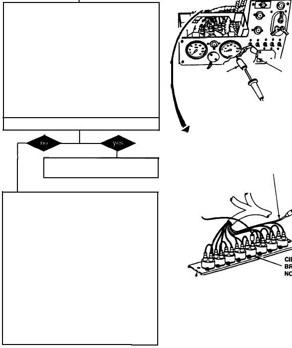
K. 1. Disconnect wire 10 from the starter switch
input.
2. Place red lead of multimeter to wire 10 of
harness 12268104 and ground black lead.
3. Turn MASTER SWITCH ON (refer to TM 9-
2350-287-1O).
4. Check for 24 ± 3 vdc.
5. Turn MASTER switch OFF (refer to TM 9-
2350-287-10).
Is voltage indicated?
Replace starter switch (para 7-9).
Verify problem is solved.
L. 1. Reconnect wire 14 of harness 12260287
and wire 10 of harness 21268104 to starter
switch.
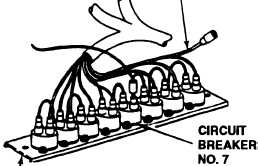
2. Disconnect wire 10 of harness 12268104
from the output of circuit breaker no. 7 on
panel no. 1
3. Place red Iead of multimeter in circuit breaker
no. 7 output and ground black lead.
4. Turn MASTER switch ON (refer to TM 9-
2350-287-10).
5. Check for 24 ± 3 vdc.
6. Turn MASTER switch OFF (refer to
2350-287-1O).
TM 9-
WIRE 10
STARTER
SWITCH
WIRE 10
OUTPUT
CIRCUM
BREAKER
PANEL NO. 1
Continued on next page
2-58