2-19. TROUBLESHOOTING CHART (continued).
I
d. ENGINE, ELECTRICAL SYSTEM (continued).
(1) ENGINE DOES NOT CRANK. All other electrical
systems operate (continued).
CONTINUED FROM E
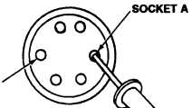
F. 1. Place red Iead of multimeter in socket A of
harness 12266418-1 starter protection relay
and ground black lead.
2. Turn MASTER switch ON and hold starter
switch ON (refer to TM 9-2350-287-10)
3. Check for 24 ± 3 vdc.
4. Release starter switch and turn MASTER
switch OFF (refer to TM 9-2350-287-10).
Is voltage indicated?
Replace starter protection relay
(para 7-3). Verify problem is
solved.
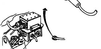
G. 1. Disconnect wire harness 12260287 from
drivers bulkhead and disconnect harness
12268418-1 from voltage regulator.
2. Place red lead of multimeter in socket T of
harness 12268418-1 driver’s bulkhead con-
nector and place the other lead on socket A of
harness 12268418-1 starter protection relay
connector.
3. Check for continuity.
4. Place red lead of multimeter in socket B of
harness 12268418-1 driver’s bulkhead con-
nector and place the other lead in socket B of
harness 12268418-1 voltage regulator con-
nector.
5. Check for continuity.
6. Place black lead of multimeter on socket B
of harness 12266418-1 starter protection re-
lay connector and leave red lead as in step 3.
7. Check for continuity.
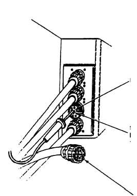
SOCKET B
STARTER
RELAY
HARNESS
12268418-1
SOCKET T
HARNESS
12268418-1
Continued on next page
HARNESS
12250287
2-55
TM 9-2350-287-20-1
SOCKET B
HARNESS
12268418-1