TM 9-2350-287-20-1
2-19. TROUBLESHOOTING CHART (continued).
d. ENGINE, ELECTRICAL SYSTEM (continued).
(1) ENGINE DOES NOT CRANK. All other electrical
systems operate (continued).
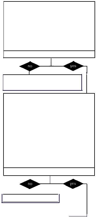
CONTINUED FROM D
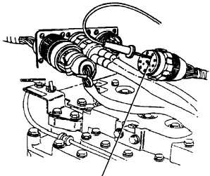
D. 2. Place one lead of multimeter in socket Pof
harness 12268418-1 engine disconnect con-
nector and place the other lead of multimeter
and in socket E of harness 12268418-1
starter protection relay connector.
3. Check harness 12268418-1 wire 14B for
continuity.
4. Is continuity indicated?
Is continuity indicated?
Repair wire 14B or replace harness
12268418-1 (para 7-44) Veril problem is
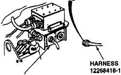
E. 1. Reconnect harness 12268418-1 to engine
disconnect bracket.
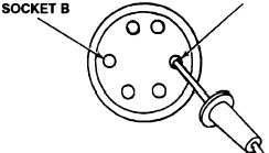
2. Place red lead of multimeter in socket B of
harness 12268418-1 starter protection relay
connector and ground black lead.
3. Turn MASTER switch ON (refer to TM 9-
2350-287-1 O).
4. Check for 24 ± 3 vdc.
5. Turn MASTER switch OFF (refer to TM 9-
2350-287-10).
Is voltage indicated?
CONTINUED AT STEP G
SOCKET P
HARNESS
12268418-1
SOCKET E
12268418-1
STARTER
RELAY
Continued on next page
2-54
solved.