TM 9-2350-287-20-1
2-19. TROUBLESHOOTING CHART (continued).
d. ENGINE, ELECTRICAL SYSTEM.
(1) ENGINE DOES NOT CRANK. All other electrical
systems operate.
Initial Setup:
Tools/Test Equipment:
Equipment Conditions:
l Digital multimeter (DMM) (Item 13, Appendix 1)
l MASTER switch set to OFF (refer to
l General mechanic’s tool kit (Item 24,
TM 9-2350-287-10).
Appendix 1)
l Transmission in “Neutral” (refer to
l STE/ ICE test equipment (Item 65, Appendix 1)
TM 9-2350-287-10).
Personnel Required: Two
l
l
l
NOTE
Instead of using multimeter forvoltage
check, STE/ICE troubleshooting,
INDIVIDUAL BATTERY VOLTAGE
TEST-TEST 89 maybe performed.
Instead of using multimeter
for continuity check, STE/lCE
troubleshooting, TEST 91 may
be performed.
Shift lever must be placed in neutral
when attempting’ engine start,
otherwise engine will not crank.
A. Perform STE/lCE troubleshooting, CHARG-
ING CIRCUIT (at battery) - TEST 67 (para 2-
22. b (8)).
Does test pass?
/
I
Recharge or replace batteries (para 7-
41). Verify problem is solved.
NOTE
If battery charge is low, perform STE/
ICE troubleshooting, TESTS 82 and
83 to be sure that alternator is
operating property.
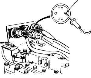
B. 1. Disconnect harness 12353401 from engine
disconnect bracket.
2. Place red lead of multimeter in socket B
and ground black lead.
SOCKET B
HARNESS
12353401
Continued on next page
2-52