TM 92350-287-10
Disconnecting Track (continued)
5.
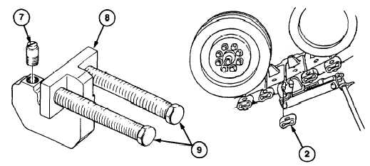
Install straight pin (7) in end connector puller (8). Install end connector puller (8) through
bolt hole in end connector (2). Puller must rest flat against end connector (2) and straight
pin (7) must engage bolt hole on both sides of end connector (2) so bolts of end connector
puller (8) engage track link pins (3). Tighten or loosen straight pin (7) until end connector
puller (8) is properly adjusted.
CAUTION
• Tighten bolts on end connector puller evenly, so end
connector is pulled evenly off track link pins. Failure to do
this can result in damage to puller and track link pins.
• When tapping end connector puller with hammer, strike
bolts squarely to avoid mushrooming the heads of bolts and
damaging the puller.
NOTE
9.
Repeat steps 5 through 8 on end connector (2) on inside of track.
To help loosen end connectors, tap bolts of end connector
pullerwith hammerwhile moving or removing end connector.
7.
Install track connecting fixture on two track link pins (3).
8.
Using end connector puller (8), remove end connector (2) from two track link pins (3). If
end connector (2) becomescocked during removal, remove end connector puller (8) and
tap end connector (2) with hammer until end connector (2) is straight on track link pins
(3). Reinstall end connector puller (8), and continue to remove end connector (2).
6.
Using end connector puller (8) 3/4-inch drive, socket wrench, and 1 1/2 inch socket,
move end connector (2) about 1 inch away from track shoe (5). If bolts on end connector
puller (8) bind, tap end connector puller bolts (9) with hammer.
Change 1
3-31