TM 9-2350-277-20-5
REPLACE WIRE ROPE AND PULLEYS (ALL EXCEPT M1064A3)
0657 00
THIS WORK PACKAGE COVERS:
Removal (page 0657 00-1).
Installation (page 0657 00-2).
INITIAL SETUP:
Maintenance Level
Unit
Tools and Special Tools
General Mechanic’s Tool Kit (WP 0926 00, Item 65)
Materials/Parts
Cotter pin (3)
Personnel Required
Unit Mechanic
References
See your -10
Equipment Condition
Engine stopped (see your -10)
Carrier blocked (see your -10)
Ramp lowered (see your -10)
Rear floor plate removed (WP 0539 00)
Wire rope disconnected from ramp cylinder
(WP 0656 00)
REMOVAL
1.
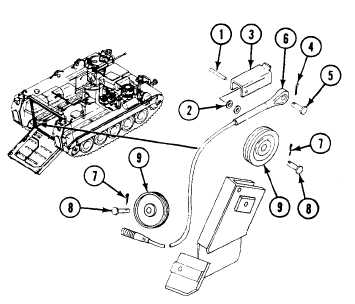
Remove pin (1), two washers (2), and guard (3) from upper pulley mount.
2.
Remove cotter pin (4), headed pin (5), and wire rope (6) from ramp mount bracket. Discard cotter pin.
3.
Remove two cotter pins (7), headed pins (8), and pulleys (9) from pulley mount. Discard cotter pins.
4.
Remove rope (6) from carrier.
0657 00-1