TM 9-2350-277-20-4
REPAIR DRIVE SPROCKET CARRIER ASSEMBLY — Continued
0421 00
INSTALLATION
1.
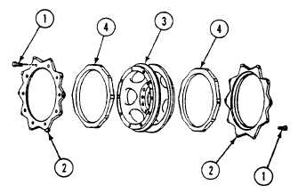
Place two cushions (4) on carrier assembly (3). Center short flat areas between mounting holes in carrier assembly rim.
Press on cushion until firmly seated against flange of carrier assembly.
2.
Place two sprockets (2) on carrier assembly (3). Secure with 20 new self-locking bolts (1). TIGHTEN BOLTS TO
110-115 LB-FT (149-156 N•m) TORQUE.
3.
Mark sprockets (2) and cushions (4) for rotation check after road test.
FOLLOW-THROUGH STEPS
1.
Install drive sprocket and carrier assembly (WP 0420 00).
2.
Connect track and adjust tension (see your -10).
3.
Install track shroud and covers (WP 0438 00).
4.
Unblock carrier (see your -10).
5.
Road test carrier to check that drive sprocket and cushion are installed right (WP 0155 00).
6.
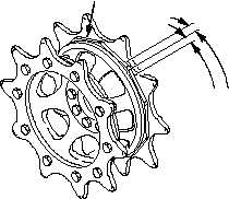
After road test, check rotation of cushion with respect to sprockets. Measure from the outer edge of the cushion. Replace
cushion that rotates beyond 1 1/2 inches (4 cm) of initial position.
1 1/2 INCHES (4 CM)
MAXIMUM
ROTATION
ALLOWED
CUSHION
END OF TASK
0421
00-2