TM 9-2350-277-20-4
REPAIR DRIVE SPROCKET CARRIER ASSEMBLY
0421 00
THIS WORK PACKAGE COVERS:
Removal (page 0421 00-1).
Installation (page 0421 00-2).
INITIAL SETUP:
Maintenance Level
Unit
Tools and Special Tools
General Mechanic’s Tool Kit (WP 0926 00, Item 65)
Torque Wrench (WP 0926 00, Item 85)
Materials/Parts
Self-locking bolt (20)
Personnel Required
Unit Mechanic
References
See your -10
Equipment Condition
Carrier on level surface
Engine stopped (see your -10)
Carrier blocked (see your -10)
Track shroud and covers removed (WP 0438 00)
Track disconnected (see your -10)
Drive sprocket and carrier assembly removed
(WP 0420 00)
REMOVAL
NOTE
The following maintenance procedure applies to one sprocket and carrier assembly only.
1.
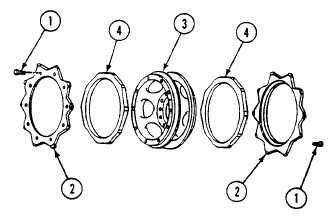
Remove 20 self-locking bolts (1) and 2 sprockets (2) from carrier assembly (3). Discard bolts.
2.
Remove two rubber cushions (4) from carrier assembly (3).
3.
If needed, repeat steps Steps page 0421 00-1 - page 0421 00-2 for other sprocket carrier assembly and cushions.
0421 00-1