TM 9-2350-277-20-4
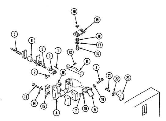
REPLACE RAMP LINKAGE (M1064A3 ONLY) — Continued
0528 00
2.
Place washers (20) and trip plate (19) on hull top plate. Make sure you install the same number of washers (20) in same
positions from which they were removed. Secure with two washers (18), new lockwashers (17), and screws (16). Do not
tighten screws until lock adjustment (Step 13).
3.
Place cross-shaft arm (1) on rear bulkhead. Secure with two support blocks (2), four new key washers (3), and screws
(4). Bend keys to secure screws.
4.
Install pin (5) in latch (6).
5.
Align spring (7), latch (6), and two washers (8) with arm (1). Secure with headed pin (9) and new cotter pin (10).
6.
Install three bumpers (11) on rod (12).
7.
Install rod (12) and three bumpers (11) in carrier.
8.
Install clevis (13) on rod (12).
9.
Align clevis (13) with arm (1). Secure with headed pin (14) and new cotter pin (15).
10. Install new locknut (16) and clevis (17) on rod (12). Do not tighten locknut until lock adjustment (Step 13).
11. Align connecting link (18) with clevis (17). Secure with headed pin (19) and new cotter pin (20). Do not bend ends of
cotter pin until lock adjustment (Step 13).
0528 00-4