TM 9-2350-277-20-4
REPLACE COMMANDER’S HATCH INTERIOR LATCH (M577A3 AND
M1068A3 ONLY)
0502 00
THIS WORK PACKAGE COVERS:
Removal (page 0502 00-1).
Installation (page 0502 00-2).
Adjustment (page 0502 00-2).
INITIAL SETUP:
Maintenance Level
Unit
Tools and Special Tools
General Mechanic’s Tool Kit (WP 0926 00, Item 65)
Socket Wrench Set (WP 0926 00, Item 72)
Torque Wrench (WP 0926 00, Item 81)
Materials/Parts
Cotter pin
Lockwasher (2)
Personnel Required
Unit Mechanic
References
See your -10
Equipment Condition
Engine stopped (see your -10)
Carrier blocked (see your -10)
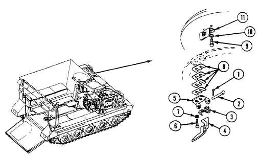
REMOVAL
1.
Remove cotter pin (1) from headed pin (2). Discard cotter pin.
2.
Remove pin (2), spring (3), and latch plate (4) from eye bracket (5).
3.
Remove two screws (6), washers (7), eye bracket (5), and spacers (8) from hull.
4.
Remove two screws (9), lockwashers (10), and strike (11) from commander’s hatch cover. Discard lockwashers.
0502 00-1