6-34
Change 4
TM 9-2350-267-34
RECTIFIER: DISASSEMBLY, INSPECTION AND REPAIR, AND ASSEMBLY (CONTINUED)
G
H
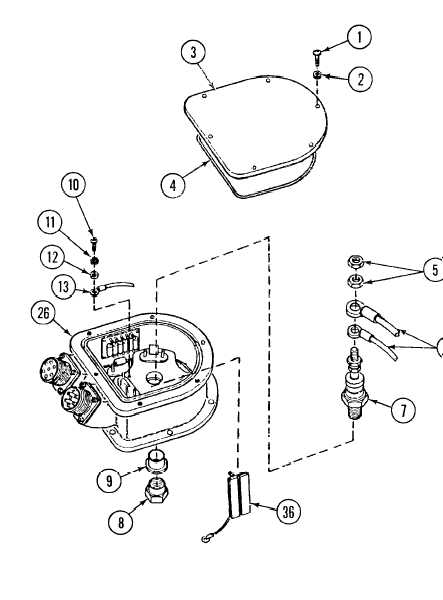
Install lead C-6 to E-3 (13) on heat sink (14) with screw
washer (11), and flat washer (12).
Install semiconductor CR-7 (7), bushing (9), and nut (8).
Install two electrical leads (6) on semiconductor CR-7 (7)
(5).
L
M
10), serrated
with two nuts
Solder electrical leads to connection points except capacitor board
assemblies (34 and 36) (p 6-26 and 6-28).
WARNING
Acetone-type solvent is toxic and flammable. Use only in
a well-ventilated area. Do not breathe vapors. Do not use
near open flame or excessive heat. Failure to heed warning
could cause SERIOUS INJURY or even death.
Clean capacitor bead assemblies (34 and 36) mounting surfaces with
acetone-type solvent (item 76, Appx B).
Install capacitor board assemblies (34 and 36) in housing (26) using
pressure sensitive tape.
Solder remaining electrical leads to connection points (p 6-26) and 6-28).
NOTE
Apply sealing compound (item 48, Appx B) to screws
prior to installation.
Install new seal (4) and cover (3) with six screws (1) and six flat washers (2).


