SHIFT CONTROL LINKAGE: ADJUSTMENT (CONTINUED)
J
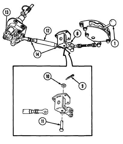
Remove cotter pin (9), flat washer (10) and clevis pin (11).
Discard cotter pin.
K Remove shift control inner tube (12) from bell crank arm (6).
L
Check base assembly (13) to ensure that the neutral safety
switch is in neutral position. Verify by trying to crank engine
after fuel shutoff has been pulled (p 5-11).
M Loosen two nuts (14),
NOTE
Keep shift selector (1) in neutral position.
N
Adjust shift control inner tube (12). Unscrew until clevis pin
(11) can be installed easily into bell crank arm (6).
O Install new cotter pin (9), flat washer (10) and clevis pin (11).
P
Tighten two nuts (14).
TA57225
7-35
Change 2
TM 9-2350-267-20