SHIFT CONTROL LINKAGE: REMOVAL AND INSTALLATION (CONTINUED)
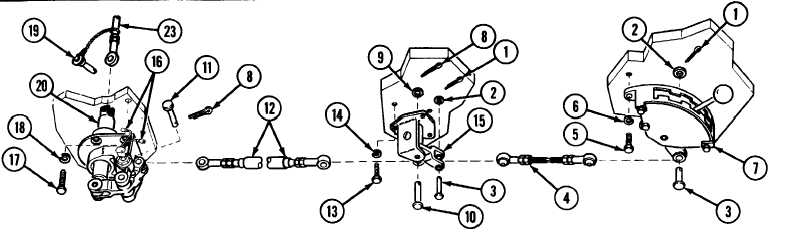
INSTALLATION
A
Install lever (38) and throttle control lever (37) and secure with
H Install support assembly (15) with three screws (13) and three
flat washer (36) and screw (35).
new lockwashers (14).
B Install spacer (34) and bell crank (33) at transmission with screw
I
Install rod assembly (12) with two pins (10 and 11), flat washer
(30), new lockwasher (31) and flat washer (32).
(9) and two new cotter pins (8).
C
Install rod assembly (29) with pin (28), flat washer (27), new cot-
J
Install quadrant assembly (7) with three screws (5) and three
ter pin (26), new lockwasher (25) and screw (24).
new lockwashers (6).
D Install rod assembly (23) with screw (21) and new lockwasher
K Install rod assembly (4) with two pins (3), two flat washers (2)
(22).
and two new cotter pins (1).
E
Install base assembly with shaft (20) with four screws (17) and
L
Close and secure both transmission doors and air intake grille.
four new lockwashers (18).
ADJUSTMENT
F
Connect rod assembly (23) to shaft (20) with quick-release pin
(19).
Refer to p 7-34 for adjustment procedures.
G Connect two push switch electrical leads (16).
TA312859
7-30.1/(7-30.2 blank)
Change 1
TM 9-2350-267-20