7-36
Change 2
TM 9-2350-267-20
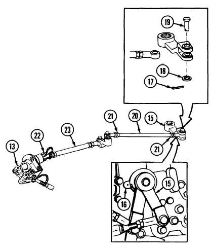
SHIFT CONTROL LINKAGE: ADJUSTMENT (CONTINUED)
Q Check that shift control lever (15) is in neutral position at shift
control lever index (16).
R Remove cotter pin (17), flat washer (18) and clevis pin (19).
Discard cotter pin.
S
Remove shift control outer rod (20) from shift control lever (15).
T
Loosen two nuts (21).
U Adjust shift control outer rod (20). Screw/unscrew to approx-
imately 8-1/4 inches, from center line bearing bore to center line
bearing bore.
NOTE
Check that shift control lever (15) is in neutral posi-
tion at index (16).
V
Disconnect quick-disconnect pin (22).
W Remove shift control outer tube (23) from base assembly (13).
X
Install shift control outer rod (20), clevis pin (19), flat washer
(18) and new cotter pin (17).
NOTE
Check that shift control lever (15) is in neutral posi-
tion at index (16).
TA57226