ENGINE COMPARTMENT AFES SENSING ELEMENT COUPLINGS: REMOVAL AND lNSTALLATION (CONTINUED)
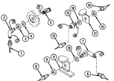
D Remove caps from elbow coupling (7). Install elbow coupling
onto bracket (11) using hex nut (9) and washer (10).
E Join sensing element (8) to elbow coupling (7) and tighten (p
14-15, 14-20 or 14-24).
F
Join sensing element (6) to elbow coupling (7) and tighten (p
14-15, 14-20 or 14-24).
G Remove caps from elbow coupling (2). Install elbow coupling
(2) onto bulkhead adapter (5) using locknut (3) and washer
(4).
H Join sensing element (1) to elbow coupling (2) and tighten (p
14-15 or 14-18).
INSTALLATION
CAUTION
Before installation, clean connector fittings
thoroughly with electrical contact cleaner (item
74, Appx D).
A Remove caps from straight coupling (13). Install straight
coupling onto bracket (17) using locknut (15) and washer
(16).
B Join sensing element (14) to straight coupling (13) and
tighten.
C Join sensing element (12) to straight coupling (13) and
tighten.
WARNING
Remove locking pin from valve actuator guard
of engine extinguisher cylinder bottle no. 2 (7, p
14-28). Turn engine T/A panel Maintenance
switch to horizontal position. Turn MASTER
switch ON to activate engine AFES.
14-26.1/(14-26.2 blank)
Change 3
TM 9-2350-267-20