14-26
Change 3
TM 9-2350-267-20
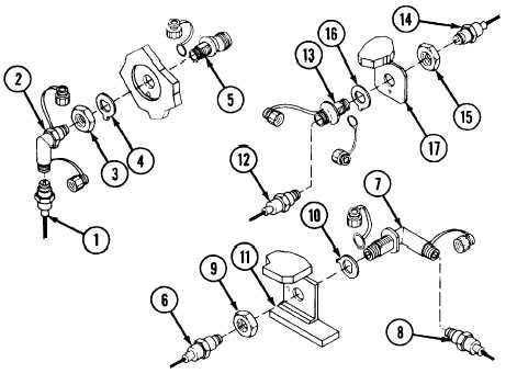
ENGINE AFES - ENGINE COMPARTMENT AFES SENSING ELEMENT COUPLINGS: REMOVAL AND INSTALLATION
REMOVAL
WARNING
Turn engine T/A panel Maintenance
switch to vertical position. Make sure
locking pin is installed in valve actuator
guard of engine extinguisher cylinder
bottle no. 1 and install locking pin in
v a l v e a c t u a t o r g u a r d o f e n g i ne
extinguisher cylinder bottle no. 2.
NOTE
When removing bulkhead couplings, remove
starter relay (p 6-45) to gain access to
coupling.
A
Disconnect sensing element (1) from elbow coupling (2). Pull
sensing element away from elbow coupling (p 14-15 or 14-
18).
B
Loosen locknut (3). Remove elbow coupling (2) and flat
washer (4) from adapter (5) at bulkhead. Cap both ends of
elbow coupling (2).
C
Disconnect sensing element (6). Pull sensing element away
from elbow coupling (7) (p 14-15, 14-20 or 14-22).
D
Disconnect sensing element (8). Pull sensing element (8)
away from elbow coupling (7) (p 14-18, 14-20 or 14-24).
E
Remove hex nut (9) and remove washer (10). Pull elbow
coupling (7) from bracket (11). Cap both ends of elbow
coupling (7).
F
Disconnect sensing element (12) from straight coupling (13)
and pull sensing element (12) away from straight coupling.
G Disconnect sensing element (14) from straight coupling (13)
and pull sensing element (14) away from straight coupling.
H
Remove locknut (15) and washer (16) from straight coupling
(13). Pull straight coupling (13) from bracket (17). Cap both
ends of straight coupling (13).