L C
INSTALL
NOTE
Make sure carrier is on level ground.
When installing driver's level indicator,
make sure cable is not pinched against
housinmg.
7 .
8.
9 .
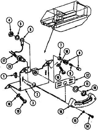
Install new plate nuts (1) with four new riv-
ets (2) on indicator bracket (3).
Install nut (4), new lockwasher (5) terminal
lug (6), ring spacer (7), lamp retainers (8),
and lamp (9) on indicator bracket (3).
Install nut (10), new lockwasher (11) marker
(12), and indicator switch (13), on indictors
bracket (3).
10. Install two screws (14), new lockwashers
(15), and level indicator (16), in plate nuts
(1) on indicator
bracket (3)
NOTE
Make sure tags are removed from leads
before installing.
11.
12.
Solder three tagged electrical leads (17) on
indicator switch (13) on indictor
bracket (3).
Install driver's level indicator bracket
assembly
(3) on bulkhead with four new
lockwashers
(18) and screws (19).
A D J U S T
13. Set up clinometeron top deck to the right
of turret, and adjuat to read side-to-side
tilt.
14. Note the reading on the clinometer.
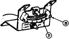
15. Loosen two adjustment screws (20) on
‘driver’s level indicator (21) adjust level
indicator to read the s a m e as the
clinometer.
TM 9-2350-261-34
16. Tighten adjustment screws (20 them recheck
driver's level indicator (21) with clinometer,
END OF TASK
8-11