R E P L A C E A U X I L I A R Y P O W E R ( S L A V E ) R E C E P T A C LE
( A L L E X C E P T M 5 7 7 A 2 A N D M 1 0 6 8)
DESCRIPTION
This task covers: Remove (page 9-2).
Install (page 9-4).
INITIAL SETUP
Tools:
General Mechanics Tool Kit (Item 30, App D)
Materials/Parts:
Gasket
Grommet
Lockwasher (early model)
Lockwasher (2) (late model)
Self-locking nut (4) (early model)
Self-locking nut (8) (early model)
Self-locking nut (4) (late model)
Self-locking nut (8) (late model)
Personnel Required:
Unit Mechanic
References:
see your -10
Equipment Conditions:
Engine stopped/shutdown (see your -10)
Carrier blocked (see your -10)
Battery ground lead disconnected (page 13-2)
REMOVE
3.
1.
2.
N O T E
Steps 1 through 5 tell you how to remove
the early model slave receptacles. Steps 6
4.
through 13 tell you how to remove the
late model slave receptacles.
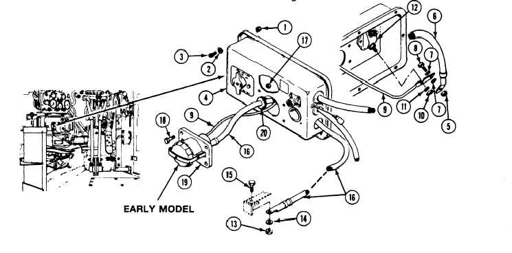
Remove eight locknuts (1), washers (2), and
5.
screws (3) from master switch panel (4). Pull
panel away from distribution box. Discard
locknuts.
Remove nut (5), circuit 49 lead (6), two
Loosen nut (10) and lockwasher (11) on
master switch (12). Remove lead (9) from
master switch terminal. Discard Iockwasher.
Remove nut (13), washer (14), screw (15),
and ground lead (16) from instrument panel
strut hull mount.
Remove four nuts (17), screws (18), receptacle
(19), and grommet (20) from panel (4).
Remove grommet from ground lead (16).
Discard grommet.
-
9-2
Change 3
TM 9-2350-261-20-2
washers (7), and screw (8) from terminal on
circuit 50 lead (9).