TM 9-2350-261-20-2
R E P L A C E P I V O T S T E E R B R A K E D I SK
INITIAL SETUP
Tools:
References:
General Mechanics Tool Kit (Item 30, App D)
See your -10
Torque Wrench (Item 96, App D)
Equipment Conditions:
Materials/Parts:
Engine stopped/shutdown (see your -10)
Self-locking nut (4)
Drive shaft removed (page 20-5)
Brake removed (page 23-68)
Personnel Required:
Carrier blocked (see your -10)
Unit Mechanic
N O T E
Left and right brake disks are removed
and installed in the same manner.
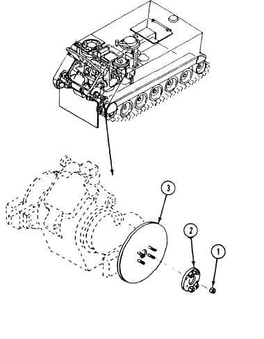
REMOVE
1. Remove four locknuts (1), adapter (2), and
brake disk (3) from differential output shaft.
Discard locknuts.
INSTALL
2. Install new brake disk (3) and adapter (2) on
differential output shaft. Secure with four
new locknuts (1). Tighten nuts to 75-80 lb-ft
(102–108 N-m) torque. Use torque wrench.
FOLLOW-THROUGH STEPS
1. Install drive shaft (page 20-5).
2. Install brake (page 23-68).
END OF TASK
23-71