TM 9-2350-261-20-2
5.1.
6.
7.
8.
9.
10.
11.
12.
13.
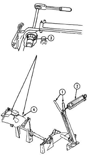
Pull back on both steering levers (1) very
hard to ensure brake adjusting nut is on
the bottom of cam.
Pull dial scale rearward.
A pull of 10-30 pounds (4.5-14 kg) on
dial scale (2) should cause steering lever
handle button to pop up. Steering lever (1)
will then move forward to release position.
Repeat adjusting procedure until you get
correct release pressure.
If adjustment cannot be obtained, notify
direct support maintenance.
If you cannot get correct release pressure,
notify direct support maintenance.
Remove socket (3) through differential
access hole.
Apply a thin even coat of antiseize com-
pound to threads of two access plugs (4).
Install two access plugs (4) in differential
housing.
FOLLOW-THROUGH STEPS
1.
Close power plant front access door and
2.
Operate carrier (see your -10). Check that
raise trim vane (see your -10).
steering brakes are operable.
END OF TASK
Change 4
21-19

