TM 9-2350-261-20-2
89.
90.
91.
92.
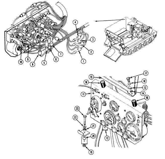
Connect circuits 21, 22, 23, and 24 leads
93.
(1, 2, 3, and 4) to front main wiring
harness.
94.
Connect circuits 450, 450B, and 451A leads
5, 6, and 7) to bilge pump switch.
95.
Connect circuit 38 lead (8) to instrument
panel wiring harness.
Connect circuit 451B lead (9) to rear bilge
pump ON indicator light.
96.
Connect circuit 28 lead ( 10) to fuel gage.
Support instrument panel ( 11) on two
struts (12).
Install ground lead (13) and new lockwasher
(14) on upper support (15). Install panel
( 11) with two mounts ( 16) on support (15).
Secure with two screws ( 17) and flat
washers ( 18).
Install panel (11) on two struts (12). Secure
with two nuts ( 19), mounts (20 and 21),
flat washers (22), and screws (23).
GO TO NEXT PAGE
12-95

