TM 9-2350-261-20-2
13.
14.
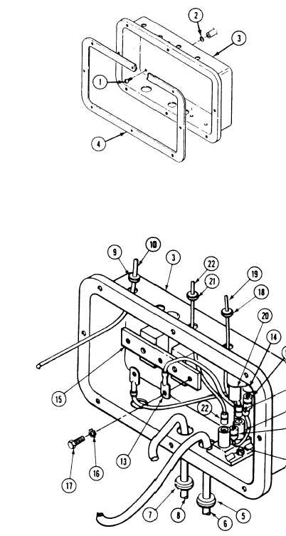
Remove five screws (1), lockwashers (2), and
distribution box (3) from hull. Discard
lockwashers.
Remove gasket (4) from distribution box (3).
Discard gasket.
INSTALL
15.
16.
17.
18.
Install distribution box (3) on hull. Secure
with five new lockwashers (2) and screws
(1). Retain new gasket (4) for later
installation.
Install new grornmet (5) and circuit 2A lead
(6) in distribution box (3).
Install new grommet (7) and circuit 2 lead
(8) in distribution box (3).
Install new grommet (9) and circuit 400
lead (10) in distribution box (3).
NOTE
If bilge pump circuit breakers were
removed,
refer
to
page
16-12
for
installation.
I f b i l g e p u m p c i r c u i t
breakers were not removed, go to step 22.
19.
20.
21.
22.
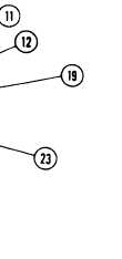
Connect circuit 450A lead (11) to circuit
breaker (12).
Connect circuit 450C lead (13) to circuit
breaker (14).
Install circuit 450C lead (13) on bus bar
(15). Secure with new lockwasher (16) and
screw (17).
Install new grommet (18) and circuit 450B
lead (19) in distribution box (3). Connect cir-
cuit 450B lead to circuit breaker (20).
Install new grommet (21) and circuit 450
lead (22) in distribution box (3). Connect cir-
cuit 450 lead to circuit breaker (23).
GO TO NEXT PAGE
12-25