TM 9-2350-261-20-2
REPLACE WARNING LIGHT PANEL ASSEMBLY
INITIAL SETUP
Tools:
References:
General Mechanics Tool Kit (Item 30, App D)
see your -10
Materials/Parts:
Equipment Conditions:
Cotter pin (2)
Engine stopped/shutdown (see your -10)
Carrier blocked (see your –10 )
Personnel Required:
Horn switch removed (page 11-24)
Unit Mechanic
Warning panel lights removed (page 11-22)
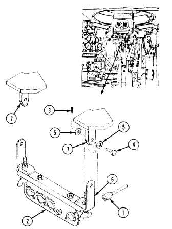
REMOVE
1, Remove five
panel (2).
2, Remove two
washers (5),
bracket (6) from hull mounts (7). Discard
cotter pins.
connectors (1) from warning light
cotter pins (3), straight pins (4),
and panel (2) with mount
INSTALL
3. Position mount bracket (6) on hull mounts
(7). Secure with two straight pins (4),
washers (5), and new cotter pins (3).
NOTE
Be sure to
lights. See
4. Install five
panel (2).
connect leads to their correct
wiring diagram (FO-2).
connectors (1) on rear of
FOLLOW-THROUGH STEPS
1. Install horn switch (page 11-24),
2. Install warning panel lights (page 11-22).
END OF TASK
11-25