TM 9-2350-261-20-2
REPLACE WARNING LIGHT PANEL
INITIAL SETUP
Tools:
References:
General Mechanics Tool Kit (Item 30, App D)
See your -10
Materials/Parts:
Equipment Conditions:
Self-locking nut (2)
Engine stopped/shutdown (see your -10)
Carrier blocked (see your -10)
Personnel Required:
Panel warning lights removed (page 11-22)
Unit Mechanic
Horn switch removed (page 11-24)
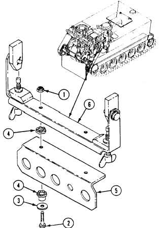
REMOVE
1. Remove two locknuts (1), screws (2),
washers (3), and four mounts (4), from
panel (5) and bracket (6). Remove panel from
bracket. Discard locknuts.
INSTALL
2. Install four
bracket (6).
screws (2),
mounts (4) and panel (5) on
Secure with two washers (3),
and new locknuts (1).
FOLLOW-THROUGH STEPS
1. Install horn switch (page 11-24).
2. Install panel warning lights (page 11-22).
END OF TASK
11-26