TM 9-2350-261-20-1
R E P A I R A I R C O N T R O L V A L V E
DESCRIPTION
This task covers:
Remove (page 7-11).
Install (page 7-12).
I N I T I A L S E T U P
Tools:
General Mechanics Tool Kit (Item 30, App D)
Materials/Parts:
Gasket
Cotter pin
Self-locking nut (3)
Self-locking nut
Personnel Required:
Unit Mechanic
Helper (H)
References:
see your -10
Equipment Conditions:
Engine stopped/shutdown (see your -10)
Carrier blocked (see your -10)
Trim vane lowered (see your -10)
Power plant front access door open
(see your -10)
Driver’s power plant access panel removed
(page 24-25)
Air cleaner hose removed (page 7-3)
Air cleaner element and housing removed
(page 7-7)
REMOVE
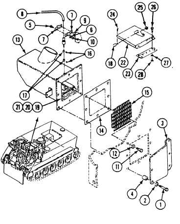
7. Remove two screws (26), washers (27),
1.
2.
3.
4.
5.
6.
Remove five screws (l), washers (2), plate
(3), and two spacers (4) from driver’s
compartment bulkhead.
Remove two screws (5), washer (6), two
clamps (7) and cable (8) from weldnut (9)
and locknut (10). Discard locknut.
N O T E
Support air control valve housing (13) at
this point to prevent its hanging by
control cable. Have helper assist.
Remove three screws (11), washers (12),
housing (13), gasket (14), and screen (15)
from driver’s compartment bulkhead. Discard
gasket.
Remove two setscrews (16) and collars (17)
to separate cable (8) from pin (18).
Remove two screws (19), washers (20), nuts
(21), baffle (22), and hinge (23) from
housing (13).
.
Remove cotter pin (24), washer (25), and pin
(18) from baffle (22). Discard cotter pin.
locknuts (28), and hinge (23) from
baffle (22). Discard locknuts.
GO TO NEXT PAGE
7-11