TM 9-2350-261-20-1
R E P L A C E L E F T C Y L I N D E R H E A D F U E L R E T U R N T U B E A N D
H O S E
DESCRIPTION
This task covers:
Remove (page 6-118).
Install (page 6-119),
I N I T I A L S E T U P
Tools:
General Mechanics Tool Kit (Item 30, App D)
Open End Box Wrench (Item 85, App D)
Materials/Parts:
Sealing compound (Item 46, App C)
Wiping rag (Item 61, App C)
Lockwasher (2)
Personnel Required:
Unit Mechanic
References:
See your -10
Equipment Conditions:
Engine stopped/shutdown (see your -10)
Ramp lowered (see your -10)
Battery ground lead disconnected (page 13-2)
Power plant rear access panel removed
(page 24-27 or 24-29).
REMOVE
W A R N I N G
Fuel flowing over a metal
surface
causes
static
electricity. This will cause a
spark unless the surface is
grounded.
N O T E
Use wiping rag to wipe up any spilled fuel.
1.
2.
3.
4.
5.
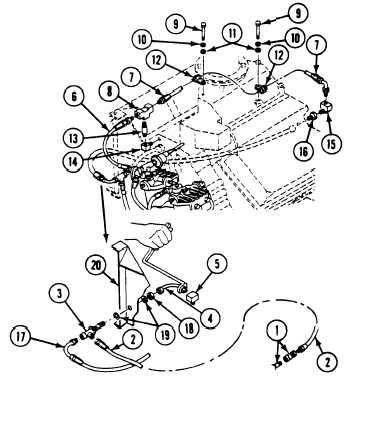
Disconnect quick disconnect couplings (1).
Remove quick disconnect coupling half (1)
from fuel return hose (2).
Disconnect fuel return hose (2) from tee (3).
Disconnect tube (4) from tee (3) and elbow
(5). Use open end box wrench.
Remove elbow (5) from left cylinder head.
N O T E
If elbow (5) is damaged do steps 6, 7,
and 8.
6. Remove hoses (6 and 7) from tee (8).
7. Remove two screws (9), lockwashers (10),
washers (11), and clamps (12) from hose
(7). Discard Iockwashers.
6-118
8.
9.
10.
11.
Remove tee (8), nipple (13), and elbow (14)
from engine.
Remove hose (7) from elbow (15). Remove
elbow (15) and coupling (16) from engine.
Disconnect air box heater fuel hose (17)
from tee (3).
Remove nut (18), two washers (19), and tee
(3) from linkage bracket (20).