TM 9-2350-261-20-1
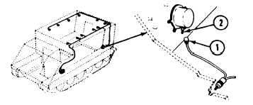
1. Remove circuit 509 plug (1) from admittance buzzer
jack (2).
2. (H) Depress admittance buzzer switch.
3. Measure voltage between circuit 509 plug (1) and
ground.
4. Does multimeter read less than 17 volts?
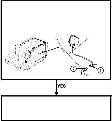
1. Remove rear main harness circuit 509 plug (1)
from admittance buzzer switch (2).
2. Install a jumper wire between admittance buzzer
circuit 509 plug (1) and ground.
3. Measure voltage across two pin contacts of circuit
509 plug (1) from admittance buzzer switch.
4. Does multimeter read less than 17 volts?
1. Turn MASTER SWITCH to OFF.
2. Remove jumper wire.
3. Repair rear main wiring harness circuit 509
(page 14-3).
4. Verify no faults found.
1. Turn MASTER SWITCH
to OFF.
2. Replace admittance buzzer
(page 12-72).
3. Verify no faults found.
1. Turn MASTER SWITCH
to OFF.
2. Replace admittance buzzer
switch (page 12-72).
3. Verify no faults found.
3-124